
RECENT UPDATES
Weather November 2023
Watts up ? November 2023
Blog 13 June
Contesting 22 May
For Sale 20 May
EME listing 22 March
70cms updated Feb '15
Kits Jan 2015
Yagis and SWR Jan 2015
In the Workshop
In the Workshop 7A
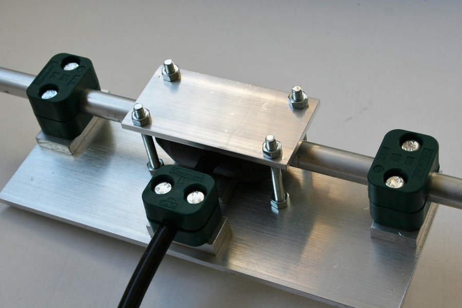
I’ve had a chance to use my Powabeam clamp and the result has been successful. With the benefit of this experience, I’ve modified the fittings so that in all places the screws are fitted permanently to the base plate because this makes it easier to drop the top halves of the clamps into place. Wing nuts have been added for speedy assembly.
If I were to make one further modification it would be to move the four screws a little further away from the dipole box. They get in the way of preparing the bottom half of the box with glue.
The clamps will be used again pretty soon because a supply of Powabeam parts arrived yesterday.

In the Workshop 7
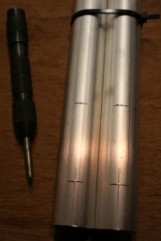
A recent addition to my web pages is the one for 70cms. On that page I describe the way in which I built a couple of yagis to a Powabeam design. It was also noted that I had the driven elements pre-assembled by Richard G6HKS.
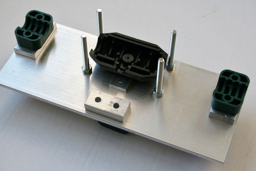
I hope to build some more of these designs, again using the Powabeam driven element assembly. So I’ve put together a clamp which will hold the parts in the right place during construction. Without this clamp, I just don’t have enough hands !
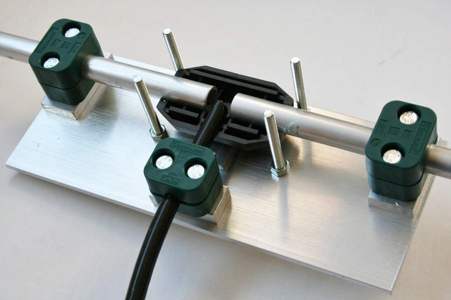
The photos are pretty self explanatory for readers who have put one of the Powabeam driven elements together - or have tried to. Essentially, three components enter the driven element moulding; the left and right dipole halves and the coaxial cable. The lower DE moulding is held to the clamp plate by its own bolt and the Stauff clamps are loosely fitted to the plate. The dipole halves and cable are then slid into in place through the clamps which are then tightened. The inner wire of the coaxial dipole can be slid through and fastened to each end. Lastly, glue can be added to the lower moulding, put the top half of the moulding in place and clamp it below the smaller plate while the adhesive sets.
The important part is to select the correct thickness of aluminium shim beneath the Stauff clamps, so that the tube height is aligned with the driven element moulding. This can be checked by looking along both dipole halves from several angles to see that it is straight from tip to tip.
This was just a mock-up for the camera. The coaxial cable is not connected to the dipoles on purpose, honest.

In the workshop 6
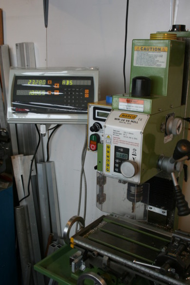
My milling machine is several years old. It’s been a great tool for providing high quality finishes to some of my products but I’ve been acutely aware that I have hardly scratched the surface of what it can do. I’ve also become aware that it’s too small for heavy engineering, and too large for model-makers precision, but never mind.
The z axis (up and down movement) is equipped with a digital readout as standard. The other two axes need measurements to be made by analogue readout as the wheels are turned. When I bought the mill I also purchased a digital readout, but didn’t fit it. On its own the digital readout is of no use – it requires a digital scale (transducer) to be fixed to two parts of the machine which are then connected to the readout. I’m not quite sure why I didn’t buy the scales earlier, but I suspect I looked at my internet shopping basket when buying the mill and thought “that’s enough for now”!
Recently I purchased and fitted digital scales to the x and y axes. It is certainly not an easy job. The scales fit any machine, but in truth they will not fit any machine without a lot of careful work. I say careful because (i) if they are fitted incorrectly the measurements can be inaccurate and (ii) if they are fitted incorrectly they can break on the first time of use (remember they are delicate items being fitted to a large heavy machine).

Thankfully, both digital scales now work nicely. They have a resolution of 0.005mm although the ultimate accuracy is less than this. My first job with digital readout installed is rather more complex than I would have chosen for a beginners piece but it’s turned out satisfactorily. It’s a heatsink for a small control board and you can see three areas of milling at two different depths together with holes of three different sizes and with two different threads, one metric and one UNC.
Perhaps I could also make a 20p coin, but I guess that each one would take me a
couple of days ...........
In the workshop 5
Simple ideas are often the best !
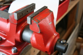
Many of us have a vice in the workshop, shed or garage and it’s invaluable. They are often equipped with tough serrated jaws to grip the workpiece without slipping.
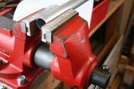
Most of my metalworking is with aluminium so those hard steel jaws (first photo) cause a bit of a problem; I don’t want the relatively soft aluminium to leave my workshop with an imprint of the vice jaws. The answer is to fit some rubber jaws (second photo). Mine have with a magnetic backing strip so that they stay in place and they were obtained from Axminster Power Tools for just a few pounds. They’re equally useful for other soft metals such as copper, for materials like nylon plate, or for holding a bolt without damaging the thread.
In the workshop 4
I recently had a request to provide a couple of new pulleys for an Altron telescopic mast. The owner sent me the old ones to allow me to copy the main dimensions. He said they were a bit worn, and that turned out to be something of an understatement. The picture below shows old and new side by side, together with a M8 bolt on which they rotate. The old pulley has seen so much use (or even abuse), that the 8mm hole has enlarged to almost 20mm.
The second pulley, not pictured, has a lot of wear on it’s outside but only in one place. Obviously, it gave up rotating a long while ago, and after that the cable wore a deep groove on one side. I’m told that the pulley problems came to light when the raising wire rope broke. I can’t say I’m too surprised.

In the workshop 3
For many purposes, an aerial boom of round
tube is a good solution. It is strong and has a low wind profile compared to
square section. But without a special jig it can be awkward to drill a series
of holes that are all in a line, and which all accurately pass through the
diameter of the tube. Holes that don’t line up will lead to elements being out
of alignment, and a small error in the hole is embarrassingly magnified by the
length of the element.
There is a simple way to do this, and I
make no claims for originality. It is necessary to have a long, flat workspace
such as a solid bench, and it is also necessary to have two pieces of the tube
that is being used, even if only one is to be drilled. They must be the same diameter.
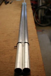
Here goes ! Place the two tubes side by
side on the bench and strap them together with cable ties. Make sure the cable
tie does not interfere with the tubes laying flat on the bench.
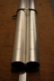
With the pair of tubes laying on the bench,
strapped together, put marks on top across the tube where the holes are to be
drilled. I use a fine tip permanent marker and white spirit can remove the mark
later if necessary. Turn the tubes over so that the first marks face the bench
and put another set of marks along the tube. Remember to work from the same end
to avoid building in errors.

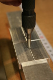
Take a metal rule (or similar), and pull it
long the top of the pair of tubes as shown in the photo. It will make a mark on
the tube and cut through the permanent marker lines. Where it cuts the line is
where the hole will be drilled. Use a centre punch at each point – automatic
centre punches are quite cheap, but not essential.
Finally, turn the tubes over and repeat the
operation with a metal rule and centre punch. The geometry of the pair of identical
tubes means that these holes will be located exactly opposite their partner.
The holes can then be drilled on the centre
punched markings. For this work, do not drill right through the tube, but work
from each face. Start with a small drill. For a few holes in a one-off boom, a
hand drill is quite adequate.

In the workshop 2
Lots of amateurs are building aerials from the designs of G0KSC, using the green Stauff insulators as element mounts. Using these mounts on a square aluminium boom guarantees that all the elements will be parallel to the face of the boom, and therefore will look good in your photos.
There is still a possibility (or certainty for some) of drilling one or both holes out of alignment with the boom centreline. The errant holes can be fudged by using a small round file, but in my opinion the only correct fitting for an oval hole is an oval bolt.
I’ve knocked up a template through which the pairs of holes can be centre-punched, which gives a much greater certainty of getting the holes in the right place and the aerial elements all aligned correctly. I’m wondering if there will be any demand if I put it in my web shop for a fiver. The prototype shown below fits 1-1/4” boom and has the hole spacing for ½” and 5/8” elements mounts, arguably the most popular sizes.
Two holes are centre-punched and drilled. The central hole is for alignment purposes and is placed over a mark made for the centre of the element position.
2 August 2013
In the workshop - Good service from Lasermaster
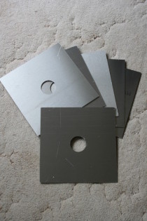
On Tuesday morning, to meet an Alimast
order, I needed to acquire to some square aluminium plates with a circular hole
in the middle. These are used for the rotator and top plates on the mast.
Previously, I have used an eBay trader
called “profilemen”, part of a company in Cornwall
called Lasermaster. On Tuesday morning I emailed my enquiry about obtaining six
aluminium sheets to my specification and before the end of the day I had
received a quote with a sensible price. Next morning I paid by Paypal, and on
Thursday morning I received an email with a tracking number for their shipment.
By Friday lunchtime I had the goods in my
workshop. As expected, they are spot-on.
It’s easy to grumble about poor (or even non-existent)
service. But it’s great to post about good service …….. maybe we should do it
more often !