
RECENT UPDATES
Weather November 2023
Watts up ? November 2023
Blog 13 June
Contesting 22 May
For Sale 20 May
EME listing 22 March
70cms updated Feb '15
Kits Jan 2015
Yagis and SWR Jan 2015
FT-847
16 December 2014
FT-847 4m Spurious transmissions
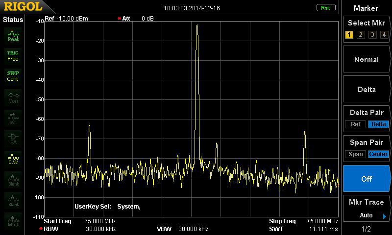
From time to time I have seen reports on the web that the FT-847 has a high level of spurious transmit signals when used on 4m. I finally remembered to put this to the test on my own rig.
In fact I have two at the moment, dating from 2002 and 2005. The results are very similar. When operating on 70.2MHz there are spurious signals on 66.5 and 73.9MHz (in other words +/- 3.7MHz) and their level is approximately 60dB down on the fundamental.
Their level does not change linearly compared to the level of the fundamental signal, and their frequency separation is not constant if the fundamental is moved.
Not quite the disaster I was half expecting, but not a brilliant result either. Being relatively close to the fundamental signal, these will not be easy to filter effectively.
13 December 2014
Are you on frequency ?
Recently, I found a need to ensure that my FT-847 was as close as possible to the correct frequency on 70cms. I had found out the hard way that it was around 500Hz adrift.
My initial attempts to check its frequency accuracy on 70cms, using the GB3NGI beacon as a source and looking at the results of its JT65B transmission did not help a lot. And cross referencing these results to the GB3VHF beacon on 2m left me more confused. It turns out that the JT65 offset for beacon stations is not standardised, and it can be quite misleading to use the DF readout in WSJT.
G4JNT has written a short guide here:-
www.g4jnt.com/Beacon_JT65_Offsets.pdf.
However, there’s a better way, and an easier way to check the frequency. It still requires the reception of a beacon, and preferably it’s one with a reliable, locked frequency source. GB3NGI and GB3VHF fall into this category.
Using USB reception, tune to where your radio frequency readout is 1kHz, exactly, below the transmitter. So for GB3VHF that is 144.429MHz. Wait for the beacon to cycle through its transmission and observe the period of steady carrier. You should hear, exactly, a 1kHz tone. The audio frequency can be checked by one of a number of soundcard applications such as Spectran, or the waterfall screen in WSJT.
Always make this check at the highest possible frequency that you have aerials available. The error is much smaller at HF, and is likely to be almost unmeasureable.
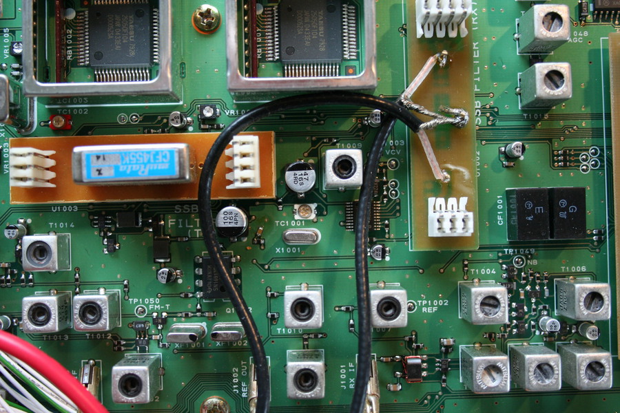
Whether the frequency is close enough is up to the reader to decide. If you want to adjust the master oscillator in the FT-847, this can be done by gently turning the capacitor TC1001 (dead centre of picture below – underside of the FT-847). “Gently” is an understatement. It needs great care and a steady hand. Also take note that excessive adjustment of TC1001 can cause the oscillator to stop, or to fail to restart. This adjustment is done at your own risk.
10 November 2013
FT-847 and Sequencing
I have put together some notes here about
my thoughts on sequencing the FT-847 in an almost foolproof manner, allowing
for all modes of transmission and a variety of assertions of PTT.
As you may have gathered, I quite enjoy
using my FT-847. True, its dynamic range is quite limited, selectivity and
sensitivity could be better and there are some curious anomalies such as no
VOX, except on CW where VOX can’t be turned off. But for a shack-in-the-box
covering 160m to 70cms including 4m, it’s hard to beat.
Talking about sensitivity, it’s pretty
essential to run external preamplifiers on 2m and 70cms. And for VHF DX-ing,
there’s often a need for more than 50w, so a power amplifier is required.
Successfully controlling these external devices so that they switch in a
controlled manner calls for a sequencer. The main requirement is that the
masthead preamplifier is switched to “through” mode before any power from the
transmitter arrives.
One way of demonstrating the sequence is:-
- PTT closes
- Preamplifier switched to through mode
- Linear amplifier turns on
- Radio goes into transmit
This is not difficult to arrange, but the
designers of most radios take steps to ensure that when the PTT is closed (step
1), the radio goes into transmit (step 4). This is not now what we want. What
follows is probably almost unique to the FT-847, because of the way it works.
Remember that as soon as the morse key is
closed, the radio will transmit. Note too that when using data (such as WSJT),
the radio PTT is controlled from the data port. There is another way of making
the radio transmit – it has a MOX button. Thankfully, due to an idea from G4DCV
and elaborated by KL7UW, there is a way to stop the FT-847 transmitting until
you are ready; ie Step 4 in the sequence above. This idea uses the Tuner port,
which has a TX Inhibit control line.
The FT-847 TX Inhibit works on all
transmission modes and for all means of PTT, whether it is from data,
microphone, key or MOX. What is required is +5 volts (at a very small current),
which is applied during receive on the Tuner port and removed as the last step
in the sequence. The diagram below shows my arrangement. This works for me and
comes with all the usual disclaimers and caveats.
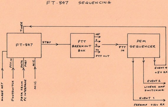
The footswitch is connected to the FT-847
PTT input so that I can control the radio in SSB when using a headset; it’s
redundant if using the stock microphone. The footswitch can also hold the rig
in transmit during CW, where I often find the maximum VOX hang delay is not
quite sufficient.
So, what happens when I go from receive to
transmit?
- The FT-847 enters transmit mode, but because TX inhibit is in
action, no RF is produced. The FT-847 keys the input of the sequencer. - Event 1 of the sequencer is to remove power from the masthead
preamp - Event 2 is to key the linear amplifier. It is “cold switched”
because no RF is reaching it yet - Event 4 is to remove the TX Inhibit control from the FT-847,
which allows it to produce RF. - Event 3 (if you’ve been paying attention) is not used.
The opposite sequence takes place when
changing from transmit to receive.
So here we have the perfect transmit
sequencer for the FT-847. Well, actually no, issues include:
~ If my TX Inhibit control cable happens to
fall out un-noticed, it’s bad news. The likely result is transmitting some RF
into the preamp. Sadly, the FT-847 provides no visual confirmation of TX Inhibit
being in use.
~ The sequencer has to be slow enough to
allow RF relays in the preamp to settle. The result of this is likely to be a
loss of the first CW character being sent. The work-around is to use the
footswitch to key the radio and not send the first character too quickly.
~ If the footswitch is accidentally hit
during a data transmission, the FT-847 gets a bit confused about where the PTT
command is coming from (data sockets or footswitch) and it usually reverts to
receive. That’s life !

10 October 2013
“POWER!” (to quote a certain motoring
presenter)
A little while ago, I obtained a second
FT-847. It was a relatively recent serial number and the previous owner had not
made any modifications. Exactly what I was looking for.
With my original FT-847 still on the bench
and working just fine, I felt confident about making some modifications to my
“new” rig which I’d considered were too invasive previously.
Top of my list is to obtain more power
output and better efficiency on 4m. The transmit power was limited to 10w out,
and to achieve this the current taken from the power supply was around 14 amps.
That is really poor. On my first FT-847 I installed a mod put forward by Keith
G4FUF, which involved inserting a ferrite core into a coil in the PA stage.
This worked well and provided about 50w maximum. For my second ‘847, I have
been more adventurous and recently carried out the PA1O modification, which
involved removing one capacitor from the PA stage.
The drawbacks to carrying out the PA1O mod
are several:- The PA board has to be removed from the transceiver to access its
underside, which in turn means that the PA transistors have to be removed with
the circuit board. Great care is needed to avoid damage, and to replace the
transistors with clean heat sink compound and the correct torque on the
mounting screws. Also, the capacitor to be removed is stuck to the circuit
board, as well as being soldered. It is a bit of a beggar to carry out a clean
removal and it wasn’t until I’d almost finished that I noticed a fine track
running under the capacitor between its two connections. It would have been so
easy for this to end in tears !
Once the capacitor is removed, a full
re-assembly has to be done prior to any testing, so it’s essential to get everything
right first time. Thankfully, I did. The final job before fastening down the
covers was to remove the “power-down” ALC mod which holds the 4m power back to
10w.
The result looks excellent. I now have
about 75w output on 4m, with some 14 amps taken from the power supply. On 6m,
just as a quick check, there is still 100w available, and the current has
dropped from 18 amps down to 16 amps.
In a few days time I’ll have access to a
spectrum analyser, and I’m keen to see if either of my FT-847’s has the dreadful
spurii that some people have noted accompany the 4m transmission.
Why do I want 75w on 4m – I have an amplifier
anyway ? Well, this year has proved beyond doubt that the amplifier is always
off at the wrong time, and three minutes valve warm-up is sometimes 2 ½ minutes
after the DX has disappeared.