
RECENT UPDATES
Weather November 2023
Watts up ? November 2023
Blog 13 June
Contesting 22 May
For Sale 20 May
EME listing 22 March
70cms updated Feb '15
Kits Jan 2015
Yagis and SWR Jan 2015
23cms
60 element yagi to G4CQM design
During Autumn 2016 I built one, and then a second yagi. A few pictures below show the aerials.
In a nutshell, the boom is 3/4" square aluminium tube. The brace is the same material and bent in a home-made jig which uses a vice to squeeze a bend into the material.
The elements are 3/16" aluminium tube, and are held in Paraclips - also a design by G4CQM. The driven element uses brass tube, forced into a machined block of PTFE. A short length of Aircell 7 cable connects the DE to the outside world. Ecoflex 15+ takes the signal to the power splitter.
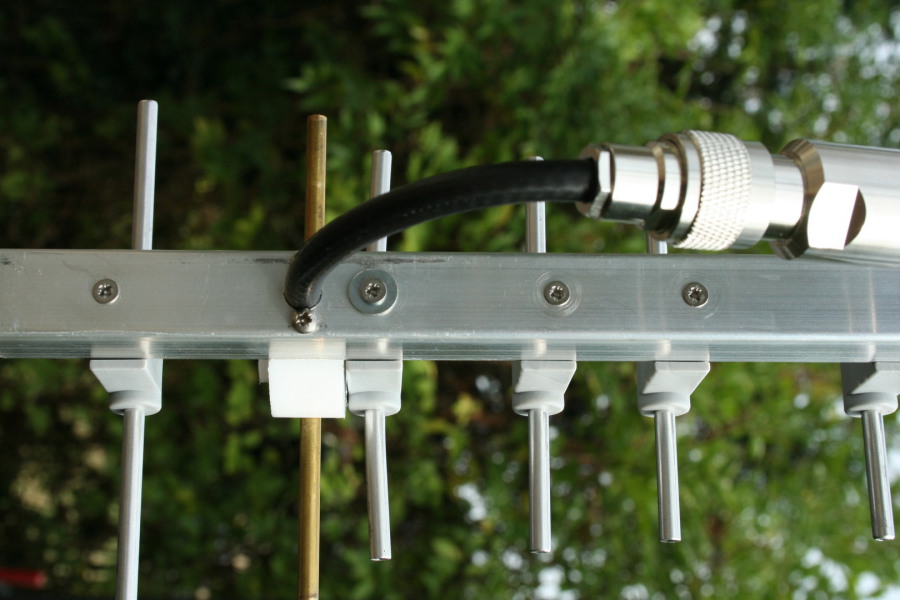
The position and length of D1 is crucial to achieving the optimum match ......... hiding under the washer is a small slot in the boom.

No boom droop here !

The support braces are formed from a single length of tube
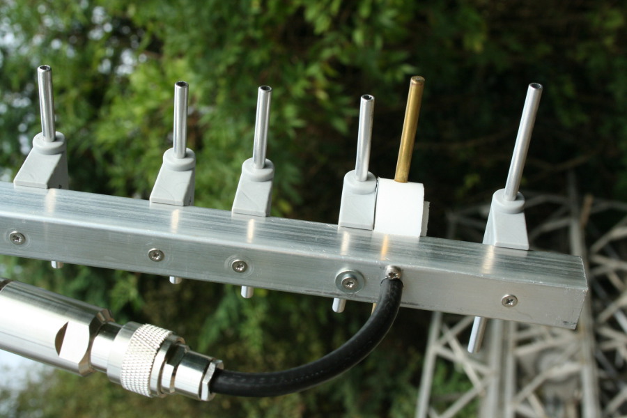
Just enough thin coaxial cable to make the bend, then into less lossy cable; Ecoflex 15+.
For VHF NFD in 2014 we fielded a set of competitive stations for the 50, 70, 144, 432 and 1296MHz bands. This year, “we” had a lot of help from the A1 Contest Group who provided a multi-array 2m station. Overall we believe the results will be good, although we have probably missed the top slot.
With a five band portable contest it’s almost inevitable that not everything will go according to plan, and one of the issues that we had was with our receive capability on 1296MHz. Put simply, there was a lot of noise on the band, dependant somewhat on beam heading and there were only a few directions where there was no noise (except that produced by the receiver). It would be an understatement to say that this noise cramped our style and contact numbers were perhaps half what we should have achieved.
Thinking back, our results on 23cms have not been what they should be for a couple of years. It’s difficult to quantify this, because each occasion is subject to individual variations of propagation and occasional changes of equipment, plus operator ability. Even our best ops have off days – yes I know it’s hard to believe. This years NFD problems have been the catalyst for further investigation and a search for a cure.
The noise or interference that we have experienced sounds exactly like an increase in preamp noise; there is no modulation and almost no change in level with respect to frequency (across the commonly used part of 23cms).
Back home, I first borrowed some equipment to get me on the band, so that I could see if I would be able to experience the same problem away from the VHF NFD site at Walton. The result quickly left me in no doubt – plenty of interference here in Colchester. This was actually good news because it meant I could take my time to seek and implement solutions without leaving home.
Secondly, I asked other local 23cms operators if they had similar experiences. Sam G4DDK and John G3XDY confirmed that they had issues and needed to install additional filtering before their mast-head pre-amps. The cause of the interference is thought to be intermodulation from either the local TV transmitter (recently gone digital at Sudbury) or increasing levels of mobile phone masts, or a combination of TV and mobile phones. I had expected that it might be Sudbury, but later discounted it because the worst level of interference happens when I am not beaming at Sudbury. In retrospect this mislead me because the polar diagram of my 1296MHz aerial is completely different at say 800MHz. Sudbury TV is line of site to my home and just 8km away. It runs 6 multiplexes between 600 and 800MHz.
Sam was kind enough to let me have a notch filter and additionally loaned me an interdigital bandpass filter at short notice. The notch filter has two stubs, notching frequencies at around 850MHz and 2100MHz. The notches are quite broad and provide attenuation of both the TV and mobile phone frequencies. When placed between the aerial and preamp on 23cms it provided a significant improvement in removing the interference. The bandpass filter provided a complete cure. It has a pass band of 850 to 1800MHz and cuts off sharply either side, with attenuation of at least 45db at 800MHz. It does not attenuate the signals from mobile phone base stations around 950MHz at all.
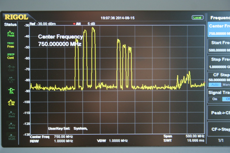
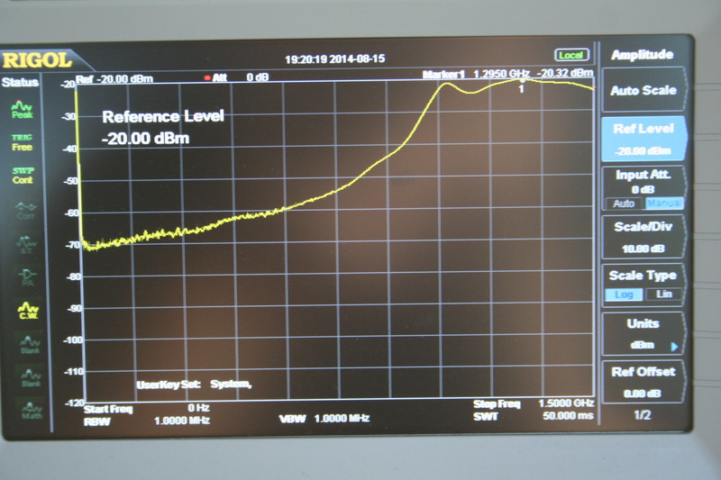
Here’s a screen shot (above) from a spectrum analyser, showing the signals received between 500 and 1000MHz on my 23cms aerial. Even though the aerials are tuned for 1296MHz, the signal levels from the TV transmitters are really strong – approaching -30dBm. Sam described these levels as “worrying” in the context of potential intermodulation.

Here’s another picture, above, this time a network analyser plot of the bandpass filter that I was lent (note the past tense – I had to return it). The scale on this plot is not quite the same as the spectrum analyser; the frequency range is 0 to 1300MHz. Attenuation is the brown trace. Just by comparing the two plots by eye (even though the frequency range is different), it can easily be seen how effective the filter is at rejecting the TV signal frequencies. Also, the through loss of the filter is very low, which means that it can be placed in front of the preamp without degrading the system sensitivity unduly.
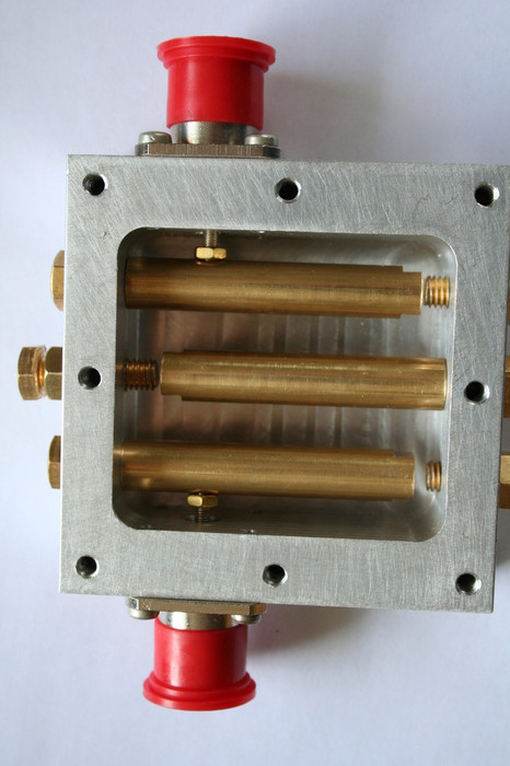
I decided to “roll my own” filter and found a programme on the internet to provide me with a design. This is the first interdigital filter I’ve made, so cautiously I chose a wide bandwidth (300MHz) with the expectation that if the design centred on 1300MHz I would be likely to end up with the 23cms amateur band somewhere inside the pass band. The other criterion was size, and because I decided to use N type connectors, the box would need to have a side at least 1 inch high. In the end, the box was milled from a solid lump of aluminium 3 x 3 x 1 inches. Drilling and milling the cavity is pretty time consuming and quite a few hours was spent getting the cavity size spot on, the brass rods trimmed to length and various holes drilled and tapped. A novel feature of construction is the use of N type sockets which have a 3mm threaded connection instead of the usual solder spill. This enabled connection to the brass filter rods without soldering (which would have been very difficult due to their size – solid 9.5mm bar).
Tuning up the filter was relatively easy, using the spectrum analyser for initial settings and then transferring the filter to a network analyser to check the input and output matching and through loss. The results looked impressive for a first time build – a through loss of about 0.25dB and SWR on each port of around 1.5 to 1. Later, with help from Sam and some decidedly better equipment to analyse the filter, the through loss improved to approximately 0.1dB.
The only fly in the ointment is the ripple of several dB within the passband, which points to an incorrect dimension. However, the region of 1296MHz falls happily on a peak of the ripple, so it’s best to leave well alone.
An analyser plot, shown below, indicates some 20dB attenuation of mobile phone frequencies around 950MHz, and 35 to 40dB attenuation of the digital TV frequencies. Recently the filter has been tested in front of two different pre-amps and the 23cms aerials and it’s good news – there is no indication of intermodulation interference with the filter in circuit.
Update on the 23cms tests
Early in September, we were in a position to test a couple of 23cms filters at the VHF NFD site while we were getting ready for the 2m Trophy contest. We had my original filter and a smaller brother, fitted with SMA’s and designed with fitting in existing preamp boxes in mind. In comparison with VHF NFD, we only had half the number of aerials up for the test, and the preamp was in the tent rather than at the masthead. Therefore, signal levels were some 4 or 5dB less. Even so, we identified the QRM, and made comparative assessments with and without filters. It’s pleasing to report that the interdigital filters removed the QRM. Therefore, the small one will be fitted into the preamp box for use in October, when we return to the site for the UHF and Microwave contest.
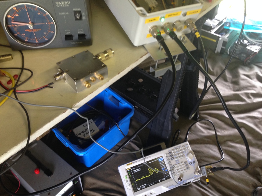
Here’s a couple of photos of testing on the bench (and floor), with thanks to Phil G0JBA.

Since then, the larger filter has been tried on air in Stowmarket, where it also provided a cure to interference. In Stowmarket, there is a choice of two TV transmitters; the one at Sudbury, and one further north at Tacolneston in Norfolk.
Through this series of tests, a variety of preamps has come under scrutiny: There is my own SSB Electronics SP-23, a DB6NT preamp, an I0JXX preamp, and a homemade preamp to the design of G0MRF. I’ve not attempted to evaluate their performance against intermodulation QRM, but suffice to say that all of them have presented the intermodulation problem to a greater or lesser extent.
Now, if only I could figure a way of making these filters quickly and cheaply. I know that they <can> be made from bits of pcb soldered together and thick wire for the filter rods, but I’m quite certain that they would not perform reliably, nor predictably, nor hold their characteristics over a long period of time. Milling the box from solid aluminium, accurately, is time consuming (and not very interesting).
Lastly, remember that a filter placed in front of the preamp will directly add to the system noise figure. This is the reason why my efforts have been directed at filters with less than 0.2dB loss. That small additional loss is, in my opinion, a very small price to pay for getting rid of the interference.