RECENT UPDATES
Weather November 2023
Watts up ? November 2023
Blog 13 June
Contesting 22 May
For Sale 20 May
EME listing 22 March
70cms updated Feb '15
Kits Jan 2015
Yagis and SWR Jan 2015
70cms
January update near the bottom of this page .........
February update at the bottom ...........
December 2014
Earlier in the year, in the “Watts Up?” pages, I explained how I have recently returned to 70cms, and have been enjoying the band. I began with a 25 element yagi from I0JXX, and later changed this for a pair of 16 elements stacked. The broader beamwidth is usually more suitable for contesting and generally listening around.
The aerials from I0JXX have excellent gain for their boom length, but in periods of heavy rain the SWR changes, and the frequency at which best SWR is achieved moves up the band. Generally, I decided this was a small inconvenience but for two reasons it seemed a good idea to look for an improvement:-
- I have a medium power solid state amplifier for 70cms and I wanted to provide it with the best possible match without quite literally having to do a weather check first,
- My long term aim is to have home made aerials on all bands.
My inquisitive nature got the better of me and I looked around at alternatives on the web. I’ve been impressed with G0KSC’s designs for the lower VHF bands, but at 70cms I have some doubts about the translation from antenna model to real world construction. So I have decided to construct a “Powabeam” or two.
Powabeams are available ready made from the DX Shop, and as kits from Richard G6HKS. In addition, the web sites of G6HKS and G4CQM (the designer), have many aerial models ready for the home constructer. Several years ago I built a 5 element Powabeam for 2m, and that worked as expected, so I had confidence in their other offerings. Common to all Powabeams is the use of a bespoke dipole mounting box, which solves the homebrewers perennial problem of weatherproofing the feed point.
Importantly, one of the selling points of the G4CQM designs is broad bandwidth and low influence by rain.
The “CQM18UC” model has a similar gain and is a similar size to the 16 element I0JXX and would be able to stack at the same distance, thus fitting the existing stacking frame, so that design was chosen for the new build.
Experience tells me that it doesn’t take much longer to build two identical items than it does one, so from the outset I undertook the measuring, cutting and drilling for the pair of aerials. Aluminium was purchased on-line from Simmal. They are not the cheapest, but they had in stock what I wanted and it arrived next day for a very sensible shipping cost. Within hours of arrival, the six lengths of aluminium were cut into dozens of short bits !
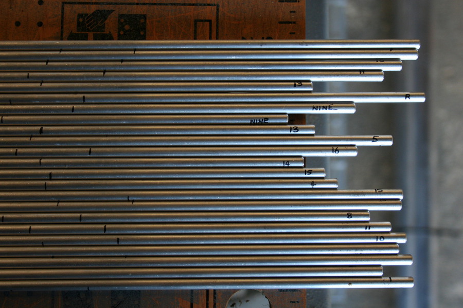
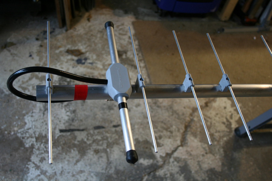
My choice for the boom was 30mm round tube with a 2mm wall thickness. With this material the boom would be in one piece and need no support (it's about 3.4m long). The elements are 3/16 inch rod. There is no choice of element size because that is what the design is modelled on, and it is the dimension of the “Paraclip” element holders. Paraclips mount on top (or below) the boom and offset the elements so that no boom correction factor is needed. For 70cms the element length needs to be controlled to within a millimetre. The photo shows a pile of elements that have been cut, checked and identified as cutting progresses. In addition they have a pair of marks near the centre of the element as a guide to centralising in the element holder. I noted that this design does not have a constant element taper, nor spacing.
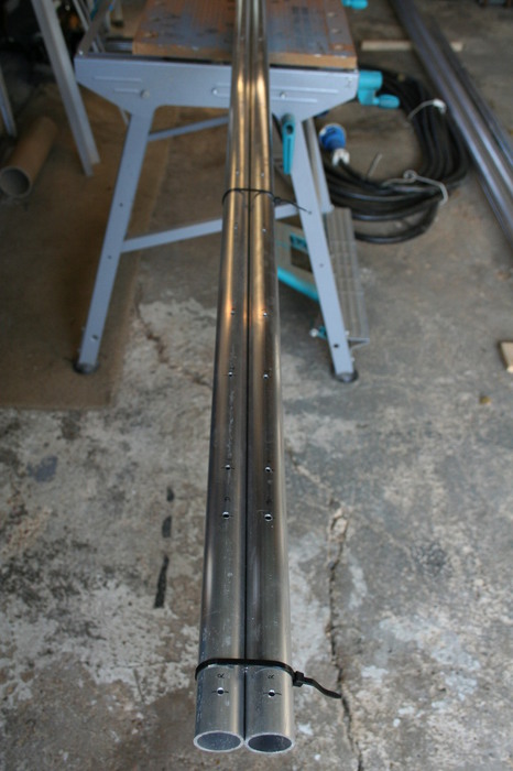
The pair of booms was marked out and drilled while clamped together. All measurements are taken from one end to minimise errors. My web pages “in the workshop” explain this in a bit more detail and show how simple it is to drill a series of neatly aligned holes in round material. Each element fixing hole is identified – this is much more foolproof than counting up as you fit the elements.
So that covers the elements and boom, and leaves the tricky bit: the driven element. Tricky because that’s how I found it some while back on the 2m build that I did. So I asked Richard if he could build the DE’s for me, and if he could ship them before Christmas – nothing like a bit of pressure. Richard agreed, and they arrived on the day before Christmas Eve. The DE’s are made from 5/8 inch tube, and feature a coaxial dipole with a coaxial tail for the user to attach an appropriate connector.
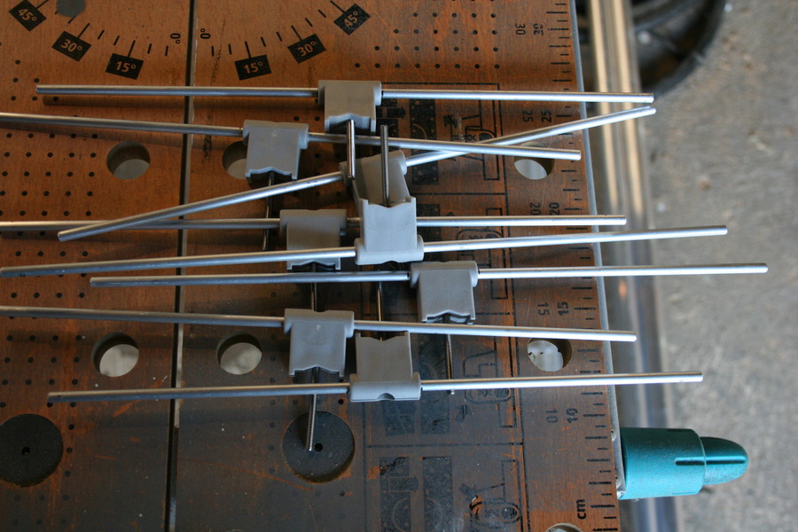
The elements are a tight fit in the Paraclips but one soon gets the hang of it. I quite soon even remembered to insert the mounting screw first, which is entirely essential. The guide marks for centering the elements were particularly useful. After a quick trial, I opted to hold the Paraclip in a machine vice, and tap the element in with a hammer, supporting the element like a long nail with the other hand. This works well on 70cms but wouldn’t be suitable for longer elements on 2m. Here’s some I did earlier.
The driven element and first director are quite close together, which means that it’s best to have the coaxial tail facing the rear of the aerial. From there it loops behind the reflector and along the underside of the boom.
It wasn’t long before one yagi was ready for a quick test to see how the SWR was shaping up. My temporary set-up for testing was less than ideal (too many surrounding objects). The SWR was around 1.35 to 1. Even given the poor test conditions, I felt this was too far adrift, noting that the design shows very close indeed to 1.0 to 1. At this point a complete check of dimensions has to take place and I concluded that all my cutting and drilling was in order.
I retired to the shack to think this over, and put the design dimensions into 4NEC2 to model the performance. The software was in clear agreement with the published design and showed an excellent match to 50 ohms. The more I looked at the driven element, the more I became convinced that all was not right, although it was difficult to tell the dipole length underneath the end caps. In a later discussion with Richard the truth dawned – the tip to tip dimension was not right. Although a modification initially looked a little awkward, it turned out to be quite a simple task of unhooking the internal wire of the coaxial dipole, cutting the outer tube to length, cutting the inner wire to length and remaking the connections.
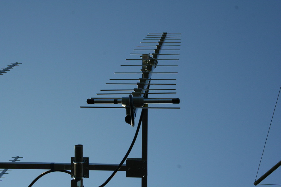
I’m writing this on Christmas Day. Having no commitments, and with the weather bright if a little chilly, I pressed on with installing the two CQM yagis with their corrected driven elements on my mast. There was no point in spending further time testing them in a less than optimum place.
Frustratingly, the SWR has improved, but not to the point where I am happy. It is now about 1.25 to 1 on each aerial tested separately and I’m convinced this design is capable of better than that. Especially as a better match can be found several MHz higher than 432.0. I’ve tried simple tricks like measuring with different patch lead lengths, but always get very similar results. But enough is enough for one day, and I’ll save further thoughts and testing for another time.
Temporarily though, there is some much better news. I have two, two way 70cms power splitters that I can use. Both, when measured with good terminations, show a decent SWR. But each one, when presented with a pair of CQM18UC yagis, behaved differently. A conventional two way, quarter wave splitter, showed an SWR of 1.38 to 1 – worse than the single yagi. In contrast, a two way half wave splitter showed an improvement to 1.10 to 1. So, for the moment, that is the one which has been installed. Measured in the shack, because of cable losses, I see an SWR of just 1.05 to 1, which is great.
Tomorrow night it’s due to rain, so I’ll be glued to the SWR meter ………
70cms Update January 2015
Some aerials incorporate a means of adjustment in the driven element, such as a Gamma or T match. Endless hours of fun can be had trying to optimise these. Matching systems inevitably incur a small amount of loss, and the Powabeam has a direct 50 ohm feed, with no matching required, no loss and no adjustment available. So is there nothing I can change ? Well, there’s always a way.
In mid-winter aerial work has to wait for the right weather, regardless of how keen one is. A suitable day dawned and combined with the need to swap out a rotator, all aerials bar one 70cms beam were removed.
I checked the match on the remaining 70cms yagi and it was 1.27 to 1. This was very much as it had been when in-situ with my other aerials, so that confirms there was no significant interaction between them.
In the meantime I have had a couple of very helpful email exchanges with Derek G4CQM. When I explained about my desire to see a better VSWR, more like the 1 to 1 seen on the design curves, he made two important points:-
- translating designs into the real world is a challenge
- a good VSWR doesn’t necessarily mean the entire aerial is resonant
In relation to the first point, he noted that an independent study had suggested that at 70cms, the effect of the Paraclips was to shorten the effective length of the elements by 1 to 2mm. Therefore, if seeking perfection, I could lengthen all the elements. Additionally, it was suggested that the driven element could be moved a little forwards or backwards to find the lowest VSWR.
Armed with these suggestions, I took one aerial into the workshop and modified all the lengths. It was hard work collecting all the swarf and sticking it back on each end to make them 2mm longer, but worth it. Of course what actually happened was that most elements could be trimmed and re-used at a different position on the boom, and just two new ones were needed. I made one additional hole in the boom to allow an option of moving the driven element forward.
To summarise, the changes made are:-
- make all elements 2mm longer
- move the DE forward about 6mm
The results exceeded my expectations and the result was good. The new longer elements produced a VSWR of 1.11 to 1 (down from 1.27). Moving the driven element forward brought the VSWR down to 1.03 to 1. The best SWR (where it’s hard to see any reflection) moved to around 433MHz. This feels like an excellent spot to have the best match, which might migrate downwards a little when it’s wet.
Talking about wet, we had lots of it on Boxing Day and I was able to look at the effect, measured at the shack end of the cable. Well, the VSWR did rise a little, and wandered around depending on how heavy the rain was, or how windy it was. I’m pretty confident that the effect was acceptable, but I held off quantifying this until I have the modified pair back up again.
Just a day after making these two changes to the aerial, there was heavy rain. The SWR gradually increased to worse than 3 to 1 and the frequency of best SWR was below 430MHz. This was bad news, and I conclude that getting the SWR right on the nose when the aerial is dry is not such a good idea. Part of the problem is that the SWR curve is much steeper HF of the design frequency, so a tolerance has to be included so that when wet, the aerial does not drift into that area. I expect some aerial wizards could explain this better, but I’ve probably made my point anyway.
To keep the aerial on the air for monitoring I have put the DE back in its design location. And I’ve delayed modifying the second aerial until a longer test in various weather conditions shows me what is happening.
Don’t let all this put you off Powabeam designs. It is simply that I thought I might find a way of improving the match and I always find it fascinating to play with aerials. If I end up back with the original design, it’s very useable and I’ve absolutely no doubt that the gain is as claimed.
70cms Update February 2015
This seems like a good time to wrap up my notes on building and using the 70cms Powabeam design.
In the January update I explained how I modified the element lengths, making them longer than the design, and how this had brought the SWR down to a really excellent value of 1.03 to 1. Then I had the smile wiped off my face because as soon as it rained heavily, the SWR rose to an unacceptable level.
Now I have gone full circle, and the aerial in use is exactly as per the design dimensions.
It’s therefore important to underline “don’t mess with someone else’s design” and “make sure there is enough tolerance in the design (and build) so that when it does rain, the aerial remains useable”.
It's also important that I rid myself of the normal engineering practice of cutting materials a bit longer than required. Because with element lengths, longer is certainly not better.
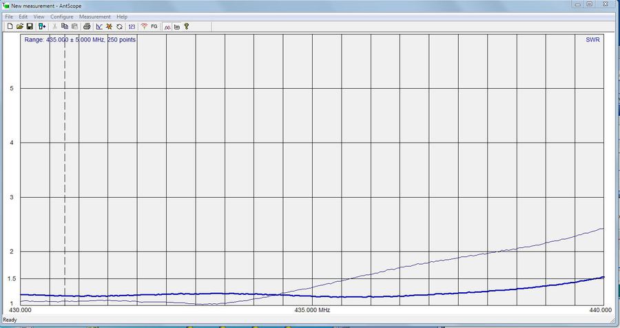
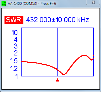
The graph below illustrates this nicely. The bold line is the SWR when dry. Note that this plot (in case it’s not clear on the screen) runs all the way from 430 to 440MHz. This is more of the band than most of us are interested in, but is necessary in order to see the full picture. On the same plot is a thin line which shows the SWR when the aerial was very wet. The entire curve has moved low in frequency by about 4MHz, but it doesn’t matter because around 432MHz the SWR is still low – in fact it has decreased.
That, therefore, brings to completion my experiments on the 70cms yagi. I’ll be carefully building the second one to match and then the pair will be brought into use on a stacking frame. Combining two aerials requires the use of a power combiner (or splitter), and that might be the subject of some further web notes in due course.