
RECENT UPDATES
Weather November 2023
Watts up ? November 2023
Blog 13 June
Contesting 22 May
For Sale 20 May
EME listing 22 March
70cms updated Feb '15
Kits Jan 2015
Yagis and SWR Jan 2015
cobwebb
Introduction
The CobWebb is a five band (14 to 28MHz)
compact array of dipoles, bent into a square, almost omni-directional and with
unity gain.
You can buy a complete CobWebb antenna,
which can be purchased on-line from the web pages of Steve Webb G3TPW, the
designer. There are also a number of copies available; some of them look rather
cheap and cheerful. Alternatively, you can build one yourself; all the
information you need is on Steve’s pages. This is the route which I took.
There are two versions of the Cobwebb and I
chose to make the one which uses single wires for each band, with a 1:4 current
balun transforming the low loop impedance back to 50 ohms. Detail for this can
be found on G3TXQ’s web pages.
Hardware
***************** News - a Cobweb hardware kit is now available in my Aerial Parts shop ***************
I have supplied friends with a hardware kit
which has formed the basis of their homebrew CobWebb antenna. They have been happy
with the results (see M0PZT web pages for example; http://www.m0pzt.com/?cobweb).
The hardware kit comprised two aluminium
plates, V bolts for mounting on a pole, Stauff clamps to hold the aluminium
tube, three lengths of aluminium tube and all the necessary nuts and bolts. I
can currently provide this to potential Cobwebb builders for £35 plus carriage.
The aluminium tubes form the central “cross” of the Cobwebb and are then
extended in a non-conductive material. The builder will need to add either
plastic or fibreglass tubes, wire for the dipoles, and the connection box and
balun. If you are interested, please contact me via email.
By the way, fibreglass can be used
throughout if you prefer, without aluminium. The Stauff clamps are great for
this because they have a large surface area for clamping – much better than U
bolts which can crush the tube.
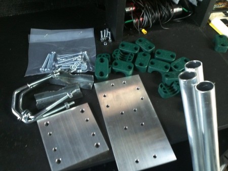 Hardware kit for the CobWebb
Construction
With a bit of spare time early in 2013 I
decided it was time to put one together myself. The metalwork was easy,
but I found that winding the 4:1 transformer and balun was surprisingly fiddly
and required an unusual combination of strength and agility in the fingers. I
took the precaution of testing each half of the transformer individually for
shorts and continuity and that worked out fine. In retrospect it would have
been easier if I had used a larger box to contain the transformer, but once it
was drilled, I was committed.
Initially I assembled the CobWebb with only
the 20m element, and placed it on a pole about 15ft high. To my relief, the
analyser showed a match of 1:1 right in the middle of the band at 14.2MHz. That’s
an excellent result and I anticipated it might change a little when the other
bands are added and when the height is increased. Temporarily, until better
weather, my own Cobwebb remained a single-bander.
It was also a droopy single bander. To keep
costs down, while being a little uncertain that it would work, I used cheap
lightweight plastic tubing to support the elements. It certainly seems to work:
My third QSO, using JT9-1 data mode was with New Zealand.
At last, in June 2013, I have found time to
complete my CobWebb. The plastic arms have been replaced with fibreglass tubes,
and wires for all bands are installed. My aluminium tube is 1” diameter with a
16g wall and I found that 22mm fibreglass tube from Sandpiper was an excellent
fit. (http://www.sandpiperaerials.co.uk).
The photos below are probably self explanatory.
Testing
Resonance was achieved first time in or
very close to each amateur band. Just a quick tweak of an inch or so was needed
to complete the job. The network analyser plot nicely shows how resonance
within each amateur band can be achieved. Note that in common with most aerials
of this type, coverage of 10m is limited to part of the band because the span
from 28.0 to 29.7MHz is too great. You can easily chose the section that you
want by trimming the dipole length.
Other bands
I could not resist the temptation to extend
the principle of the Cobwebb a little, and added an element for 6m. It runs
rather close to the ends of the aluminium tubes which form the central part of
the aerial, so performance would be compromised a little. In fact it did not
work for me: The far ends of each dipole element did not come near to closing
the loop, which is a simple feature of the geometry caused by the location of
the feed box.
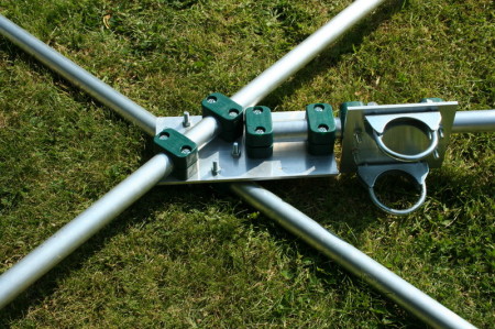 Fittings at the centre of my CobWebb: aluminium plates, U bolts, Stauff clamps and aluminium tubes
 The box at the feed point- note that the crimp connectors are marked with the frequency, to avoid confusion ! Wires are crimped and soldered.
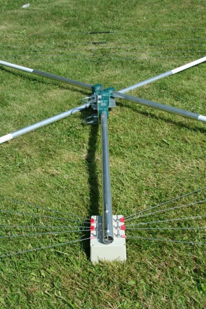 General view showing the feed point box mounting and aluminium tubes with fibreglass extensions
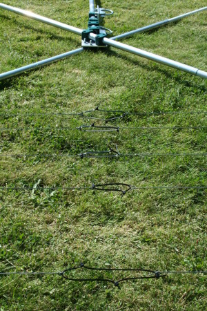 The dipole ends, separated and tensioned by cable ties. Easy but not too elegant.
| Band | Frequency range MHz |
Cobwebb resonance MHz |
Best SWR | 3:1 SWR bandwidth |
| 20m | 14.000 - 14.350 | 14.150 | 1:1.18 | 380kHz |
| 17m | 18.068 - 18.120 | 18.070 | 1:1.05 | 360kHz |
| 15m | 21.000 - 21.450 | 21.120 | 1:1.08 | 270kHz |
| 12m | 24.890 - 24.990 | 24.960 | 1:1.13 | 360kHz |
| 10m | 28.000 - 29.700 | 28.390 | 1:1.06 | 280kHz |
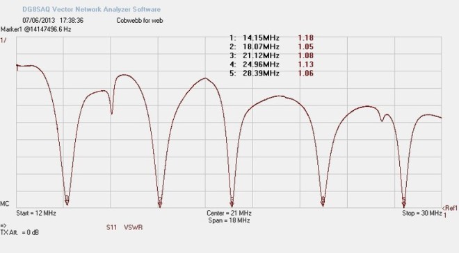 Here's the SWR plot of the five bands covered - it's a credit to the designer !
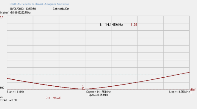 SWR on the 20m band (the horizontal dotted red lines are 1:1 and 3:1).
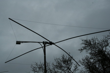
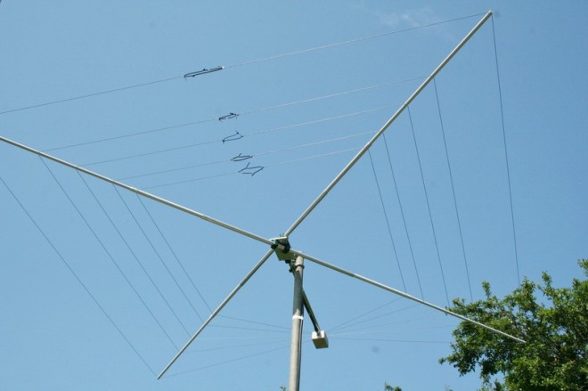 Up in the air, this time with all five bands, and no droop in the arms
Bad weather stops play
Yesterday I thought the HF bands seemed
particularly quiet. After a while it occurred to me to check the SWR of my
CobWebb and sadly all is not well. It had been raining and I waited a while to
see if water on the elements or insulators was the culprit. Things did improve
a little as it dried out but clearly it was not performing as it should. Today
I took it down (only a moments work) and found that there was some water in the
balun box. Perhaps it got in there at the weekend when we had some
exceptionally heavy precipitation.
I’ve dried out the box and left it to air
for a while, but the SWR is still poor. I can only conclude that some moisture
has got into the thin coaxial cable used in the balun. I’m going to leave it
for a few days, testing it occasionally, to see if it will dry out further – I
really want to avoid rewinding the transformer. A couple of drain holes have
been added too.
To avoid further ingress of water I’ve
turned the aerial up the other way, with the balun box on top of the tube. I
can’t think why I didn’t install it that way first time. But I suspect that water
came in around the RF socket mounting point, so it could be a good place to put
a gasket of exterior grade sealant next time it comes down.
The effect of rain
A further day on and I’m pleased to see
that the aerial SWR has returned almost to normal, which must mean that the
inside of the balun box has dried out. As I write, it has just been raining
heavily again, so I’m now able to quantify the effect of rain on the aerial
elements:
When wet, the resonant point on all bands
has shifted low in frequency. It is more noticeable on the higher bands, but on
all 5 bands it turns out to be approximately 1%. For example, resonance in the
dry was set to 14.14 MHz, and when wet this shifts to 14.00MHz. The resonance
is quite sharp so the upper part of 20m becomes unusable when it’s wet. This is
not a criticism, just a statement of my findings.
It would be worth considering cutting the
elements to resonate a little above ones desired frequency in the dry, to
partly mitigate the effect of rain on the elements. Despite this, I still like
this compact multiband aerial a lot !